DRV8434 Stepper Motor Driver Carrier
Option:Unsoldered (loose headers)
Price:
Sale price
£9.40
Stock:
Quantity:
 Skip to content
Cart
Your cart is empty

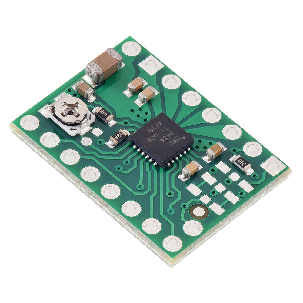

This Pololu breakout board for TI’s DRV8434 microstepping bipolar stepper motor driver offers microstepping down to 1/256-step and operates from 4.5V to 48V. It can deliver up to approximately 1.2A continuous per phase without a heat sink or forced air flow (2A peak).
The driver has inputs for setting the decay mode and includes two smart tune current regulation modes that help you achieve smooth steps without manual tuning. The module has a pinout and interface that are very similar to that of our popular A4988 carriers, so it can be used as a drop-in replacement for those boards in many applications. It features built-in protection against under-voltage, over-current, and over-temperature conditions.
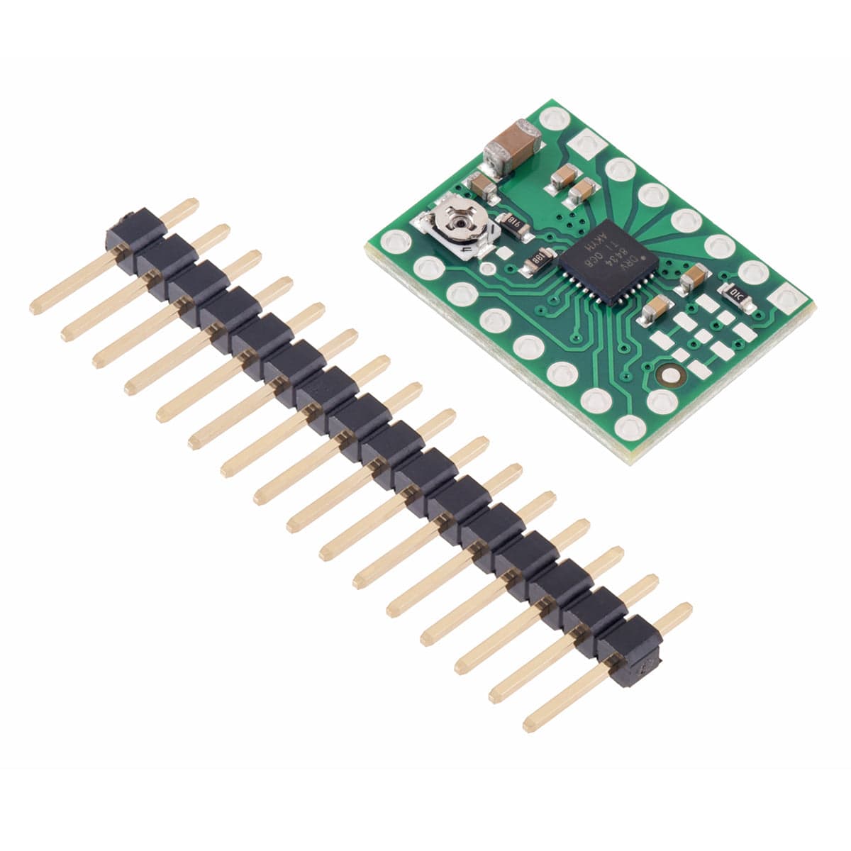
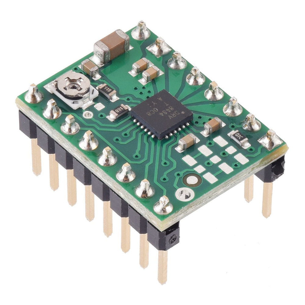
We offer this board with headers pre-soldered, or unsoldered with headers included in the package. Please select the desired option before adding to cart.
WARNING: This product can get hot enough to burn you long before the chip overheats. Take care when handling this product and other components connected to it.
This product is a carrier board or breakout board for the DRV8434 stepper motor driver from Texas Instruments (TI); we therefore recommend careful reading of the DRV8434 datasheet before using this product. This stepper motor driver lets you control one bipolar stepper motor at up to approximately 1.2 A continuous per phase without a heat sink or forced air flow (see the Power dissipation considerations section below for more information).
Note: Some unipolar stepper motors (e.g. those with six or eight leads) can be controlled by this driver as bipolar stepper motors. For more information, please see the frequently asked questions. Unipolar motors with five leads cannot be used with this driver.
Note: available with or without headers pre-soldered. Please select an option before adding to cart.

The driver requires a motor supply voltage of 4.5 V to 48 V to be connected across VIN and GND. This supply should be capable of delivering the expected stepper motor current. Note that supply voltages below 6 V limit the maximum settable current limit; see the Current limiting section for more details.
Four, six, and eight-wire stepper motors can be driven by the DRV8434 if they are properly connected; an FAQ answer explains the proper wirings in detail.
Warning: Connecting or disconnecting a stepper motor while the driver is powered can destroy the driver. (More generally, rewiring anything while it is powered is asking for trouble.)
Stepper motors typically have a step size specification (e.g. 1.8° or 200 steps per revolution), which applies to full steps. A microstepping driver such as the DRV8434 allows higher resolutions by allowing intermediate step locations, which are achieved by energizing the coils with intermediate current levels. For instance, driving a motor in quarter-step mode will give the 200-step-per-revolution motor 800 microsteps per revolution by using four different current levels.
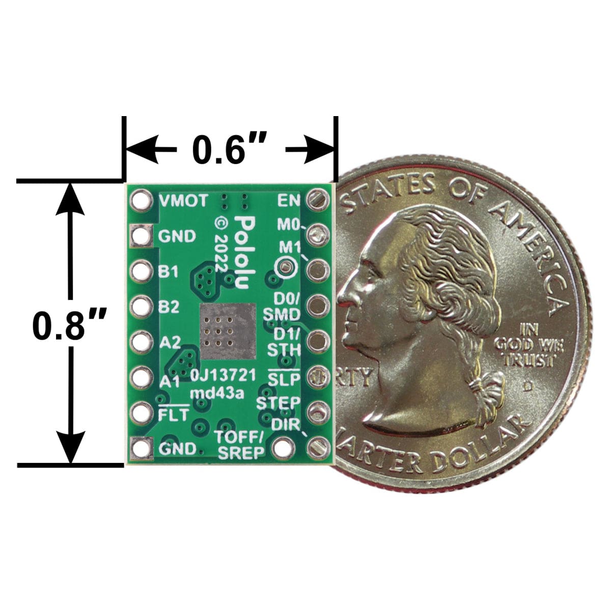
The resolution (step size) selector inputs (M0 and M1) enable selection from the eleven step resolutions according to the table below. M0 is a tri-level pin and M1 is a quad-level pin; note that the voltage on these pins must be greater than 2.7 V for them to register as logic high. The driver defaults to 1/128 step mode. For the microstep modes to function correctly, the current limit must be set low enough (see below) so that current limiting gets engaged. Otherwise, the intermediate current levels will not be correctly maintained, and the motor will skip microsteps.
| M0 | M1 | Microstep Resolution |
| Low | Low | Full step with 100% current |
| Low | 330kΩ to GND | Full step with 71% current |
| High | Low | Non-circular 1/2 step |
| Hi-Z | Low | 1/2 step |
| Low | High | 1/4 step |
| High | High | 1/8 step |
| Hi-Z | High | 1/16 step |
| Low | Hi-Z | 1/32 step |
| Hi-Z | 330kΩ to GND | 1/64 step |
| Hi-Z | Hi-Z | 1/128 step |
| High | Hi-Z | 1/256 step |
The rising edge of each pulse to the STEP input corresponds to one microstep of the stepper motor in the direction selected by the DIR pin. These inputs are both pulled low by default. If you just want rotation in a single direction, you can leave DIR disconnected.
The decay inputs (DECAY0 and DECAY1) allow for selection from six current decay modes according to the table below. Both pins are tri-level pins; note that the voltage on these pins must be greater than 2.7 V for them to register as logic high. The driver defaults to smart tune dynamic decay mode. The TOFF pin is used to set the fixed off time for all modes except smart tune ripple control mode, where it instead sets the allowed ripple current. See the datasheet for more details.
| DECAY0 | DECAY1 | Decay Mode for increasing steps | Decay Mode for decreasing steps |
| x | Hi-Z | Smart tune dynamic decay | Smart tune dynamic decay |
| Low | Low | Smart tune dynamic decay | Smart tune dynamic decay |
| Low | High | Smart tune ripple control | Smart tune ripple control |
| High | Low | Mixed decay: 30% fast | Mixed decay: 30% fast |
| High | High | Slow decay | Mixed decay: 30%fast |
| Hi-Z | Low | Mixed decay: 60% fast | Mixed decay: 60% fast |
| Hi-Z | High | Slow decay | Slow decay |
The chip has two different inputs for controlling its power states: SLEEP and ENABLE. For details about these power states, see the datasheet. SLEEP (SLP) is internally pulled-low which by default prevents the driver from operating; this pin must be high to enable the driver (it can be connected directly to a logic “high” voltage between 1.8 V and 5 V, or it can be dynamically controlled by connecting it to a digital output of an MCU). A 20 μs pulse on the SLEEP pin clears latched faults without putting the driver to sleep. The default state of the ENABLE (EN) pin is to enable the driver. ENABLE is also used to select whether the overcurrent protection and thermal shutdown operate in latched shutdown or automatic retry mode. See the datasheet for more details.
The DRV8434 also features an open-drain FAULT output that drives low whenever the driver detects an under-voltage, over-current, open load, stall detection, or thermal shutdown fault. The carrier board connects this pin to the SLEEP pin through a 10 kΩ resistor that acts as a FAULT pull-up whenever SLEEP is externally held high, so no external pull-up is necessary on the FAULT pin. Note that the carrier includes a 1.5 kΩ protection resistor in series with the FAULT pin that makes it is safe to connect this pin directly to a logic voltage supply, as might happen if you use this board in a system designed for the pin-compatible A4988 carrier. In such a system, the 10 kΩ resistor between SLEEP and FAULT would then act as a pull-up for SLEEP, making the DRV8434 carrier more of a direct replacement for the A4988 in such systems (the A4988 has an internal pull-up on its SLEEP pin).

To achieve high step rates, the motor supply is typically higher than would be permissible without active current limiting. For instance, a typical stepper motor might have a maximum current rating of 1 A with a 5 Ω coil resistance, which would indicate a maximum motor supply of 5 V. Using such a motor with 9 V would allow higher step rates, but the current must actively be limited to under 1 A to prevent damage to the motor.
The DRV8434 supports such active current limiting, and the trimmer potentiometer on the board can be used to set the current limit. You will typically want to set the driver’s current limit to be at or below the current rating of your stepper motor. One way to set the current limit is to put the driver into full-step 100% current mode and to measure the current running through a single motor coil without clocking the STEP input.
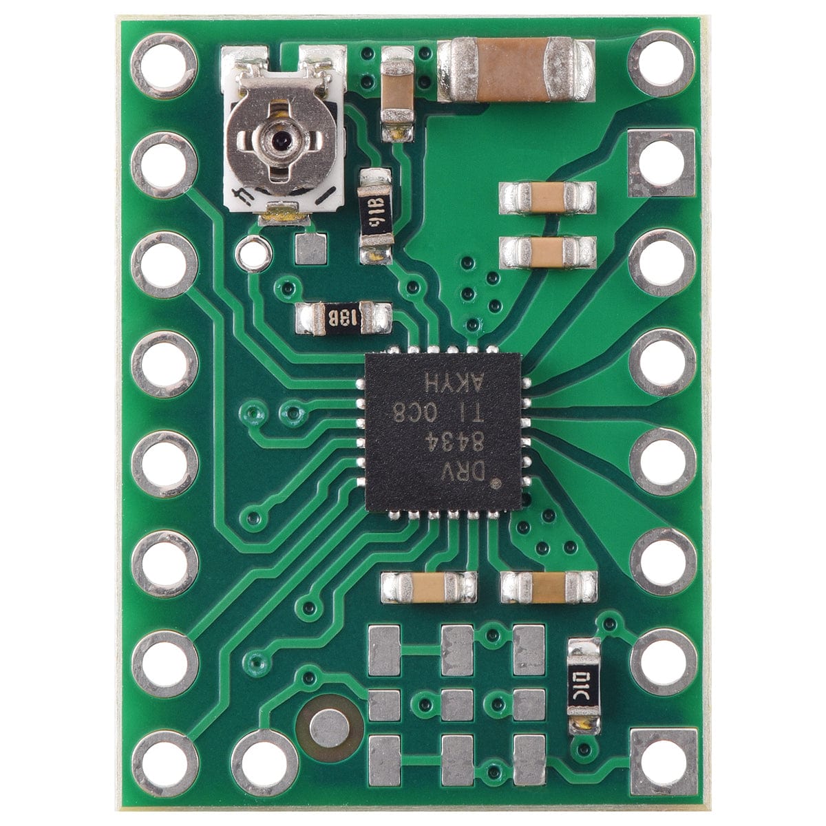
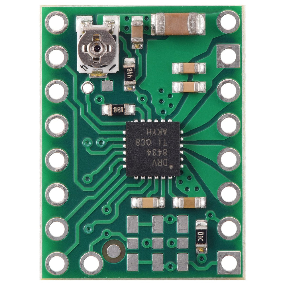
Another way to set the current limit is to measure the VREF voltage and calculate the resulting current limit. The VREF pin voltage is accessible via a small hole that is circled on the bottom silkscreen of the circuit board. The current limit in amps relates to the reference voltage in volts as follows:
Current Limit = VREF / 1.32
or, rearranged to solve for VREF:
VREF = Current Limit x 1.32
So, the current limit in amps (A) is equal to VREF voltage in volts (V) divided by 1.32, and if you have a stepper motor rated for 1 A, for example, you can set the current limit to about 1 A by setting the reference voltage to about 1.32 V.
For input voltages below 6 V the DRV8434’s internally regulated logic voltage VDVDD linearly drops from 5 V with a 6 V input to around 4.35 V with a 4.5 V input. VDVDD supplies the potentiometer circuit used to set the driver’s current limit, so using supply voltages below 6 V reduces the maximum current limit setting possible with the onboard potentiometer. With an input of 4.5 V the maximum settable current limit is 1.75 A.
Note: The coil current can be very different from the power supply current, so you should not use the current measured at the power supply to set the current limit. The appropriate place to put your current meter is in series with one of your stepper motor coils. If the driver is in full-step 100% current or full-step 71% current modes, both coils will always be on and limited to 100% or 71% of the current limit setting, respectively. If your driver is in one of the microstepping modes, the current through the coils will change with each step, ranging from 0% to 100% of the set limit. See the DRV8434 datasheet for more information.
The DRV8434 carrier has a maximum current rating of 2 A per coil, but the actual current you can deliver depends on how well you can keep the IC cool. The carrier’s printed circuit board is designed to draw heat out of the IC, but to supply more than approximately 1.2 A per coil, a heat sink or other cooling method is required.
WARNING: This product can get hot enough to burn you long before the chip overheats. Take care when handling this product and other components connected to it.
Please note that measuring the current draw at the power supply will generally not provide an accurate measure of the coil current. Since the input voltage to the driver can be significantly higher than the coil voltage, the measured current on the power supply can be quite a bit lower than the coil current (the driver and coil basically act like a switching step-down power supply). Also, if the supply voltage is very high compared to what the motor needs to achieve the set current, the duty cycle will be very low, which also leads to significant differences between average and RMS currents. Additionally, please note that the coil current is a function of the set current limit, but it does not necessarily equal the current limit setting as the actual current through each coil changes with each microstep.
We offer this DRV8434 stepper motor driver carrier board in two variants:
For the unsoldered variant, the headers can be soldered in for use with solderless breadboards or 0.1″ female connectors. You can also solder your motor leads and other connections directly to the board.
Your payment information is processed securely. We do not store credit card details nor have access to your credit card information.