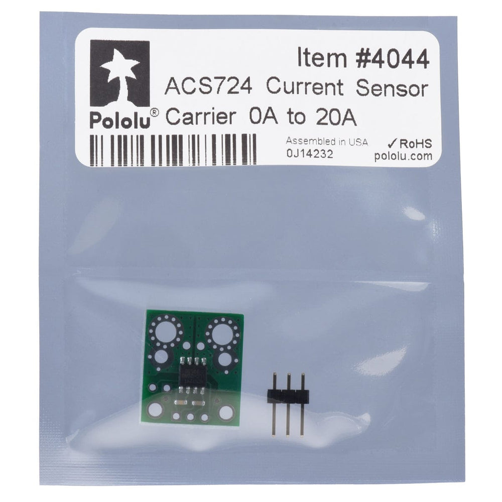
Pololu ACS724 Current Sensor Carrier 0A to 20A
Price:
Sale price
£11.30
Stock:
Quantity:
 Skip to content
Login / Signup
Cart
Your cart is empty


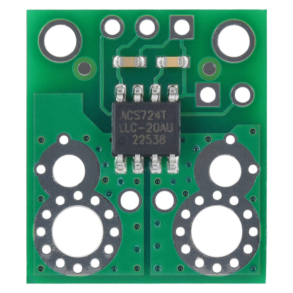
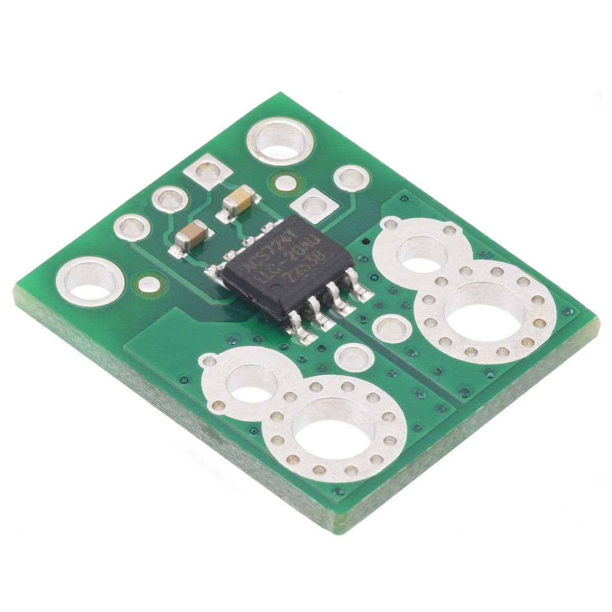
This Pololu board is a simple carrier of Allegro’s unidirectional 20A ACS724LLCTR-20AU Hall effect-based linear current sensor, which offers a low-resistance (~1.2 mΩ) current path and electrical isolation up to 2.4 kV RMS.
This version accepts a unidirectional current input up to 20A and outputs a proportional analog voltage (200 mV/A) that measures 500mV when the input current is zero. The typical output error is ±0.7%. It operates from 4.5V to 5.5V and is intended for use in 5V systems.
Warning: This product is intended for use below 30V. Working with higher voltages can be extremely dangerous and should only be attempted by qualified individuals with appropriate equipment and protective gear.
This current sensor is a carrier board or breakout board for Allegro’s ACS724LLCTR Hall effect-based linear current sensors; we therefore recommend careful reading of the ACS724 datasheet before using this product.
A number of different versions of this carrier are available, which all share the same key features.
This carrier features the ACS724LLCTR-20AU, which operates at 5V and is designed for unidirectional input current from 0A to 20A. When Vcc is 5V, the output voltage is offset by 500mV and increases by 200mV per amp of input current.

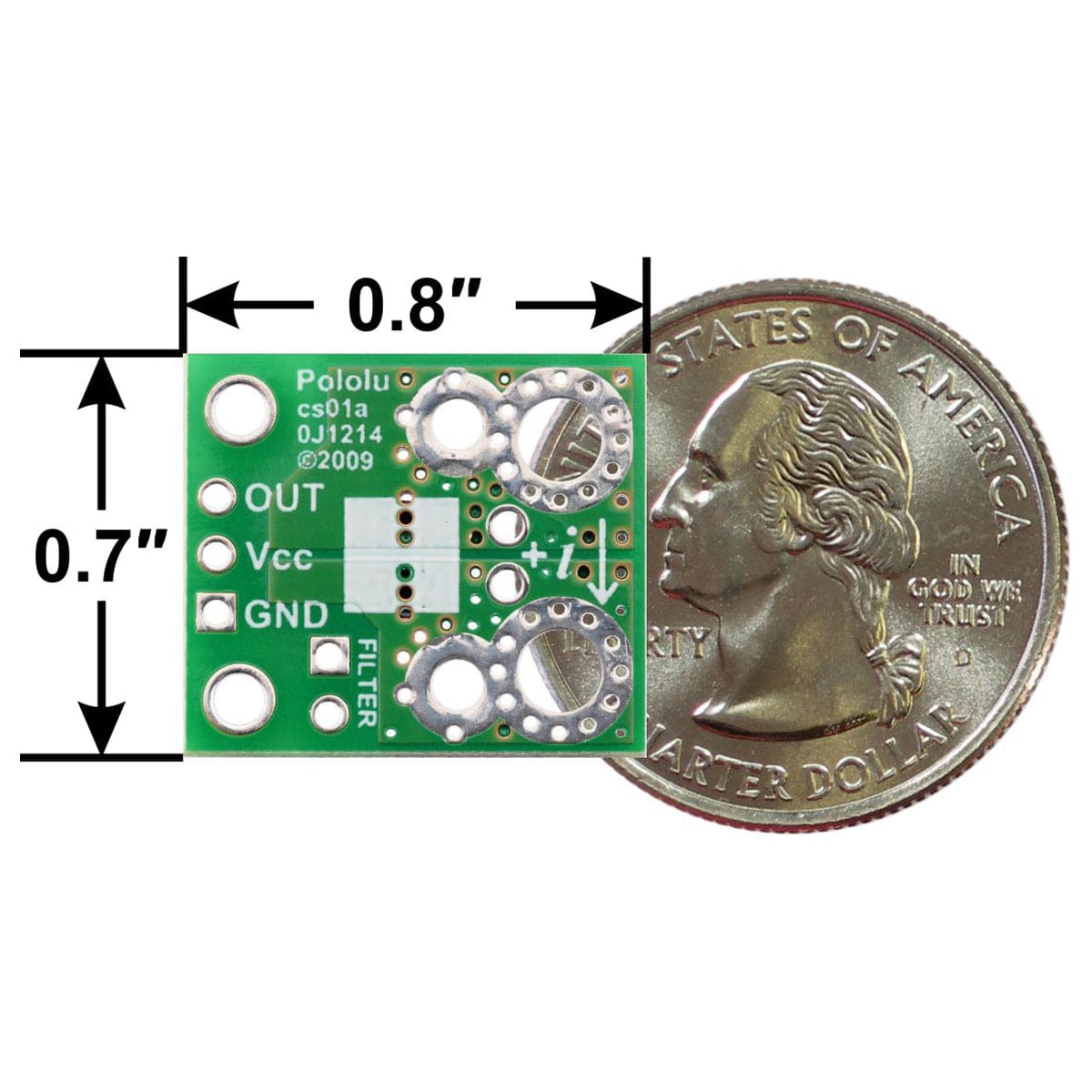
This sensor has five required connections: the input current (IP+ and IP-), logic power (VCC and GND), and the sensor output (OUT).
The sensor requires a supply voltage of 4.5 V to 5.5 V to be connected across the VCC and GND pads, which are labeled on the bottom silkscreen, and the sensor outputs an analog voltage that is linearly proportional to the input current.
The FILTER pin lets you adjust the board’s bandwidth by adding a capacitor to ground (a ground pad has been added next to the FILTER pin for convenience) in parallel with the 1 nF capacitor that is already on the board. Without an added external filter capacitor, the bandwidth is about 90 kHz. The datasheet provides more information on how the filter capacitors affect bandwidth.
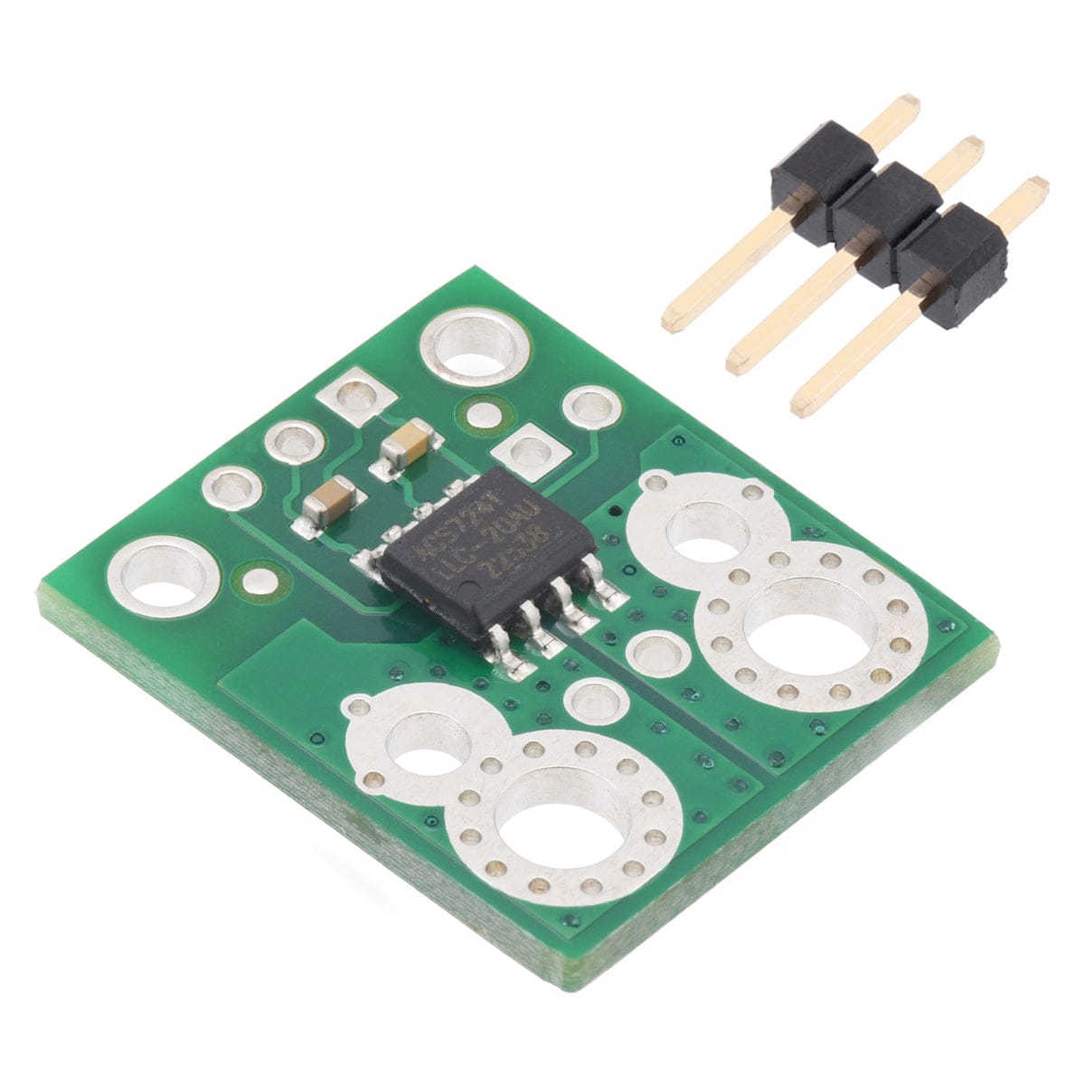
You can insert the board into your current path in a variety of ways. For low-current applications, you can solder 0.1″ male header pins to the board via the smallest pair of through-holes on the input-current side of the board. For higher-current applications, you can solder wires directly to the through-holes that best match your wires, or you can use solderless ring terminal connectors. The largest pair of through-holes are big enough for #6 screws.

Warning: This product is intended for use below 30V. Working with higher voltages can be extremely dangerous and should only be attempted by qualified individuals with appropriate equipment and protective gear.
This board ships assembled with all surface mount components, and a 3×1 strip of 0.1″ header pins is included but not soldered in.
Your payment information is processed securely. We do not store credit card details nor have access to your credit card information.