Adafruit NeoRGB Stemma - NeoPixel to RGB PWM LEDs and Strips - STEMMA JST PH 2mm
Price:
Sale price
£4.70
Stock:
Quantity:
 Skip to content
Login / Signup
Cart
Your cart is empty
Whenever we're working with 'true analogue' LED strips, that have 1-3 channels of RGB or White LEDs, we wish we had already invented to make wiring them easier: controlling these strips takes a bit of wiring since they almost always need 12VDC and driver FETs. Now, we've finally created the Adafruit NeoRGB Stemma board - which will make our lives easier, and maybe even some customers too!
The NeoRGB is a no-soldering, plug-and-play STEMMA board with a 2mm JST PH connector on one end, and a 5-pin 0.1" screw terminal block on the other. It can convert standard 5V 800KHz NeoPixel signal using a WS2811F chip to AO3406 N-channel FETs that are high efficiency and can sink a chunk of current - 3 Amps a piece with 50milliOhm Ron!
Basically, this means that you can treat any PWM-able common-anode RGB LED strip or LED as a single NeoPixel, at up to 16V and 3 Amps per channel. Perfect for large analogue LEDs or arrays, LED strips, even ones that are not RGB, such as controlling 3 independent single-channel LEDs or strips. Note that the WS2811 bare chips don't support 4 channels, so this won't work on RGBW strips. Also, the WS2811 really wants 5V logic signals so please use a level shifter if on a 3V microcontroller!
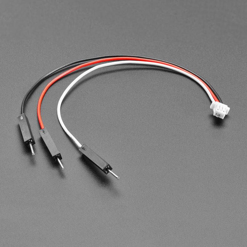
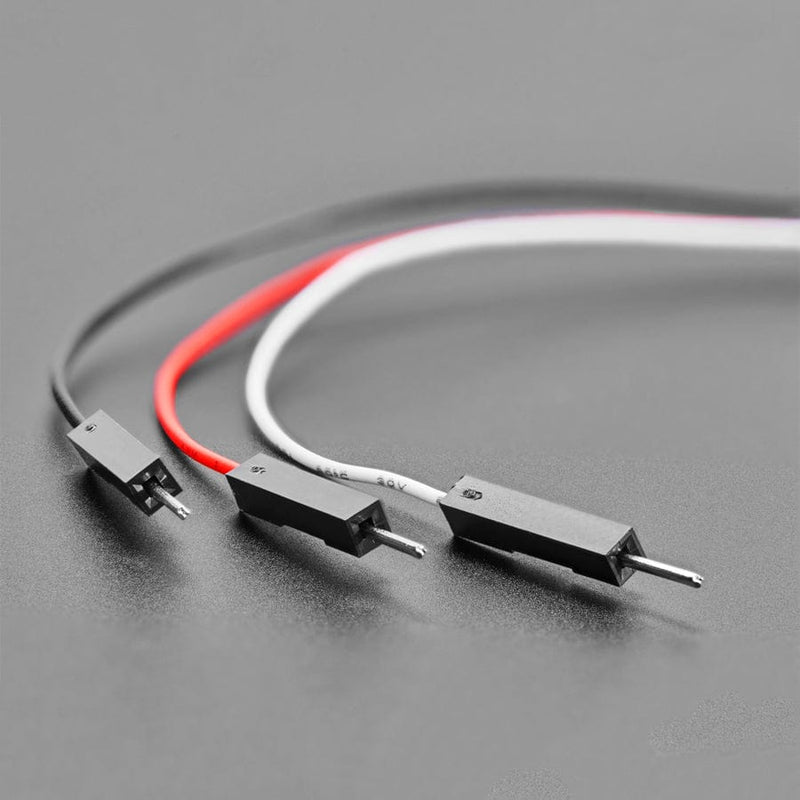
Usage is easy. First, you'll need a 2mm JST PH cable, such as this one with pins. Then pick one of two powering options
If you are using less than 2A of the current total across all 3 channels:
If you are using more than 2A of the current total across all 3 channels, you'll need to wire the power supply to the terminal block since JST PH connectors are only rated for 2A.
An onboard green ON LED will let you know that it is powered correctly, and a red Signal LED will lightly blink when data is sent on the Signal line. If you need to chain more than one or want to connect some other NeoPixels to the output, there's a pin for the Output signal on the board.
Your payment information is processed securely. We do not store credit card details nor have access to your credit card information.